 English
 Chinese
Articulated manipulators play a huge role in boosting production capacity and ensuring accuracy in manufacturing industries. The problem is that such machinery can work effectively only due to advanced neural networks, namely a Robot Arm Control System. Such a control system ensures synchronized sub-millisecond movements, trajectory corrections, and safety measures. The following guide provides the key concepts, hardware components, motion workflow, and selection criteria of control systems in modern robot arm control systems.
1. What Is a Robot Arm Control System?
1.1 Definition and Key Features
A robot arm control system is the engine that is used to manage, control, and implement movements of a robotic manipulator. This system deciphers the user instructions or predefined industrial routines, processes the inverse kinematics algorithm, and generates high-frequency electronic pulses to control the speed, axis positioning, acceleration, and spatial orientation of the manipulator joints.
1.2 Effect on the Operations
In an industrial manufacturing environment, the Robot Arm Control System plays the role of a “brain”. It defines the repeatability that is achieved within tolerances of ±0.02 mm to ±0.05 mm and minimizes mechanical oscillation during high-speed operations. Without an efficient Robot Arm Control System, the most advanced physical components will not be able to achieve the required precision and stability during operation.
2. Key Components of a Robot Arm Control System
The Robot Arm Control System consists of four interconnected sub-systems:
2.1 Main Controller
The main controller plays the role of a processing unit and performs calculations. It is built from industrial PCs (IPCs), PLCs (Programmable Logic Controllers), or special multi-axis motion control cards.
- Kinematic Processing: This component performs inverse kinematics algorithms, S-curve acceleration profile calculation, and multi-axis interpolation algorithms.
- Cycle Speed: Advanced controllers operate on interpolation cycle periods under 1 ms to generate new coordinate values.
2.2 Drive System & Servo Drives
Servo drives are devices that act as a mediator between microelectronic logic operations and actual power output through the conversion of electronic signals to modulated current.
- Closed-Loop Control: They implement cascaded control systems comprised of loops for current, velocity, and position.
- Bandwidth & Damping: State-of-the-art drives have velocity loops with bandwidth greater than 2.0 kHz to dampen mechanical resonances.
2.3 Actuator System & Motors
Joint drives transform electric current into mechanically controlled rotations. Joint actuators include lightweight AC servo motors paired with backlash-free speed reducers such as harmonic or RV gears.
Torque Transformation: Through the use of high gear ratios (varying from 1:50 to 1:160), quick revolutions of the motor can be used to create high output torque and lower joint velocity.
2.4 Feedback & Sensor Architecture
Sensors are the final element needed to complete closed-loop control and provide constant information on the physical state of the machine to the drive electronics.
- Positioning: Multiturn absolute encoders with 17-bit to 23-bit resolution provide millions of pulses per revolution of the shaft.
- Safety Integration: Force-torque sensors, safety light curtains, and 2D/3D vision sensors provide crucial information to ensure correct operation and human safety.
3. How Do These Robot Arm Control Components Work Together?
3.1 Closed-Loop Data Flow
Real-time execution within the Robot Arm Control System occurs instantaneously through the following steps:
- Path Calculation: The main controller computes angular positions of joints over time based on target coordinates.
- Transmission: Movement commands are transmitted through the deterministic fieldbuses such as EtherCAT and CANopen with speeds up to 100 Mbps.
- Power Output: The drives modulate pulse-width modulation (PWM) to rotate joint motors along the desired vector.
- Feedback: Encoders measure positions of shafts at microsecond intervals and send back data to correct the error.
3.2 Real-World Application in Injection Molding
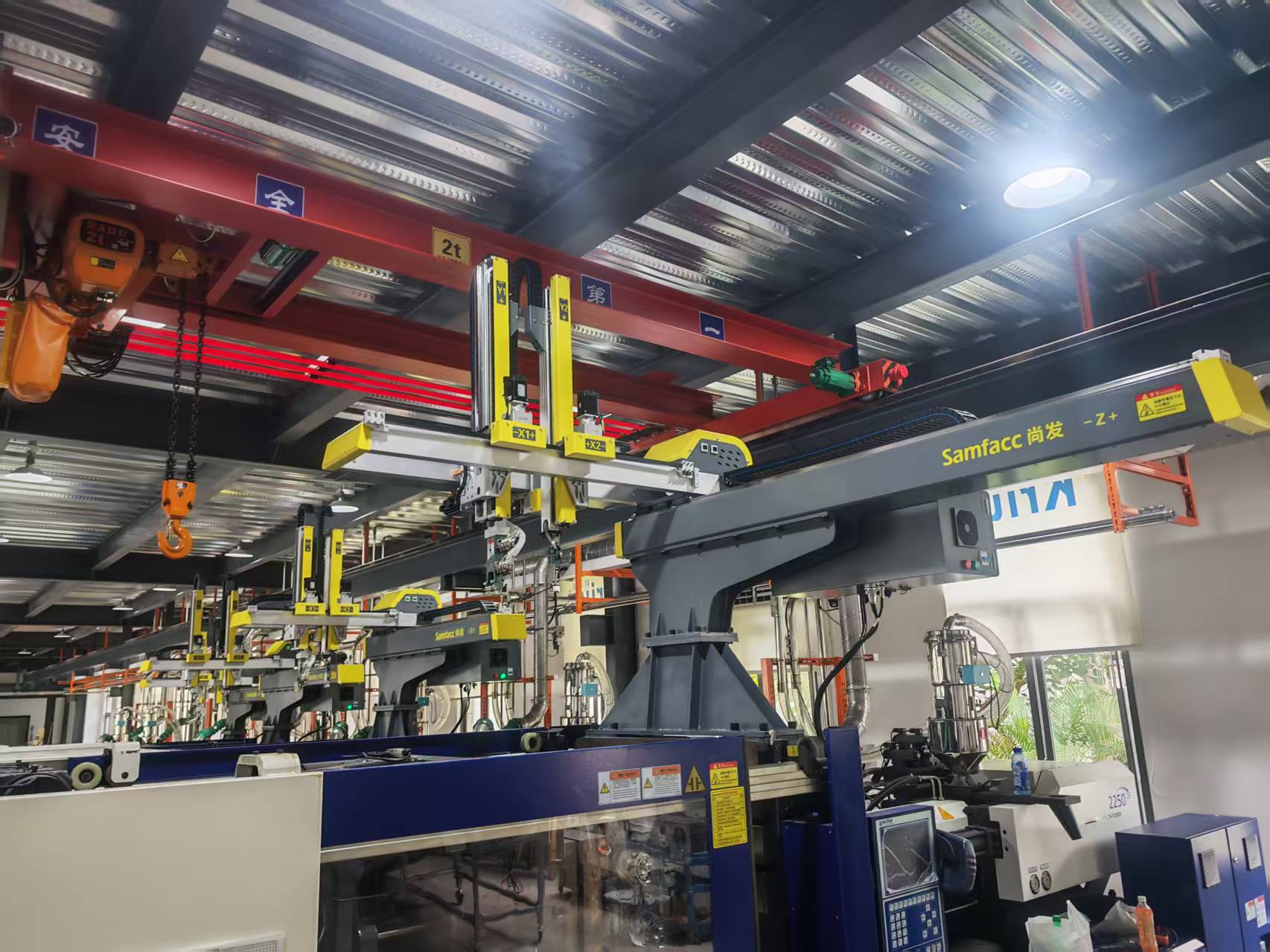
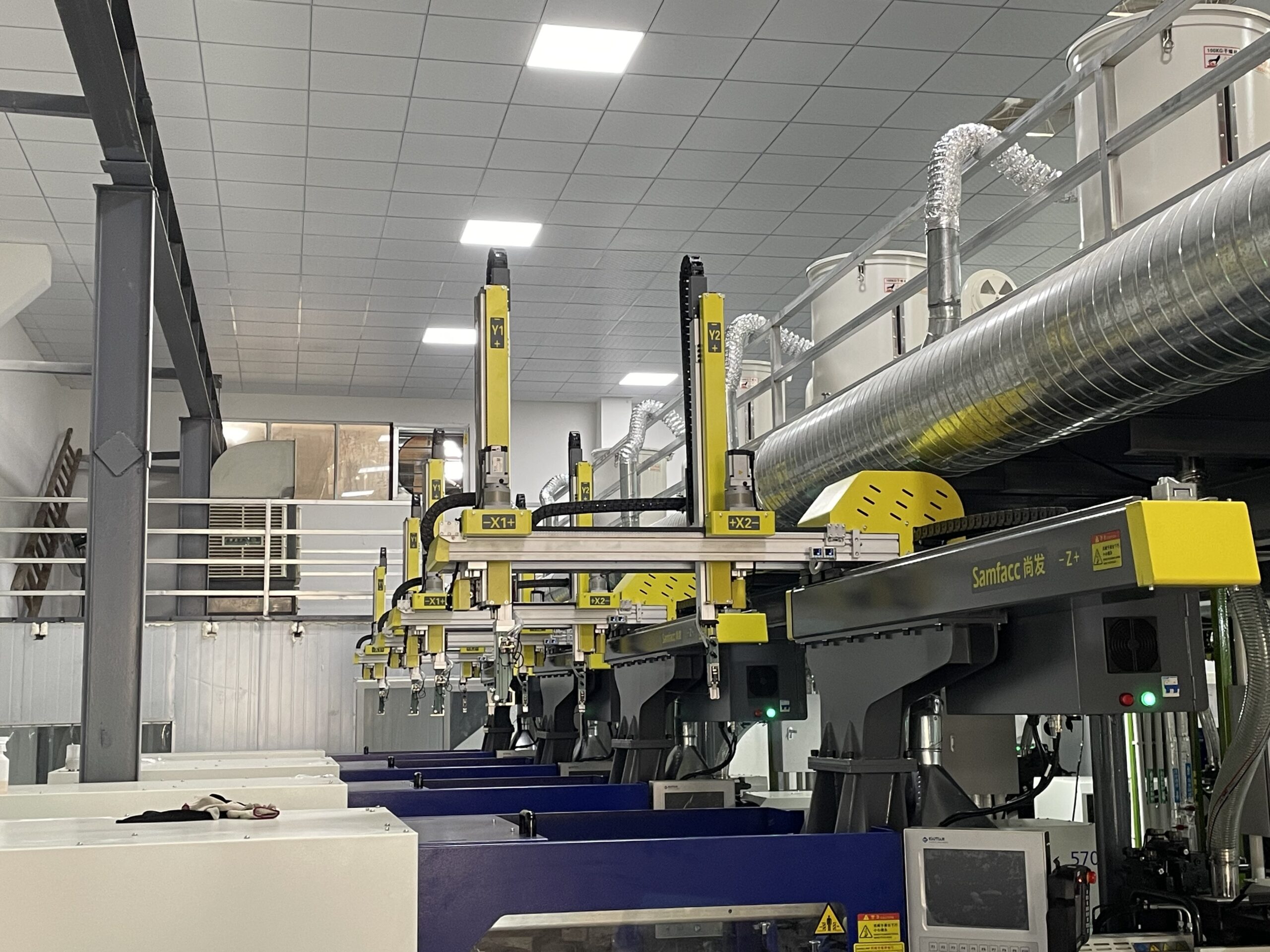
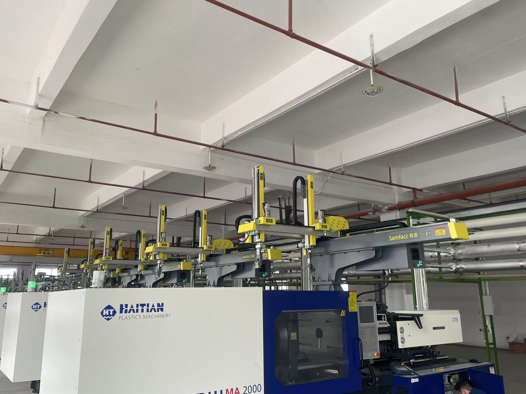
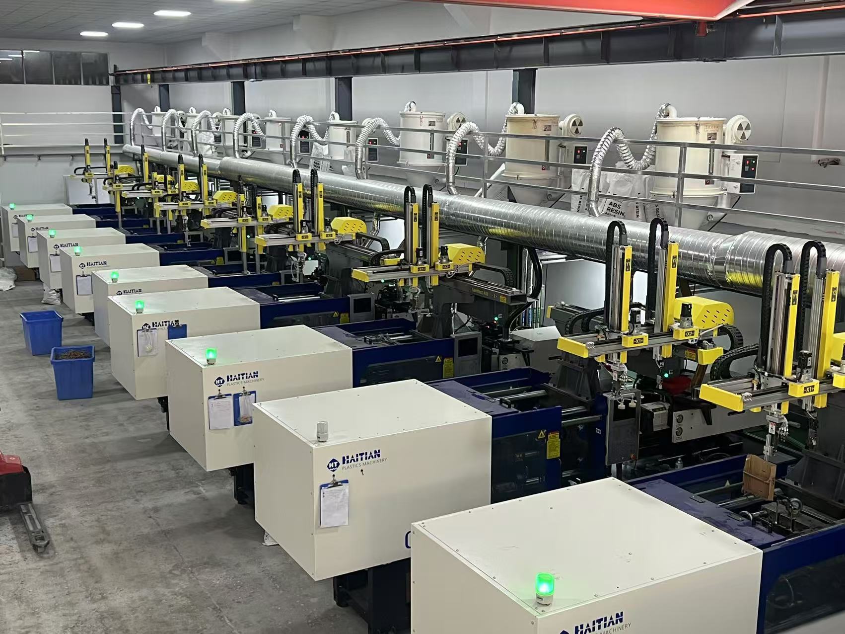
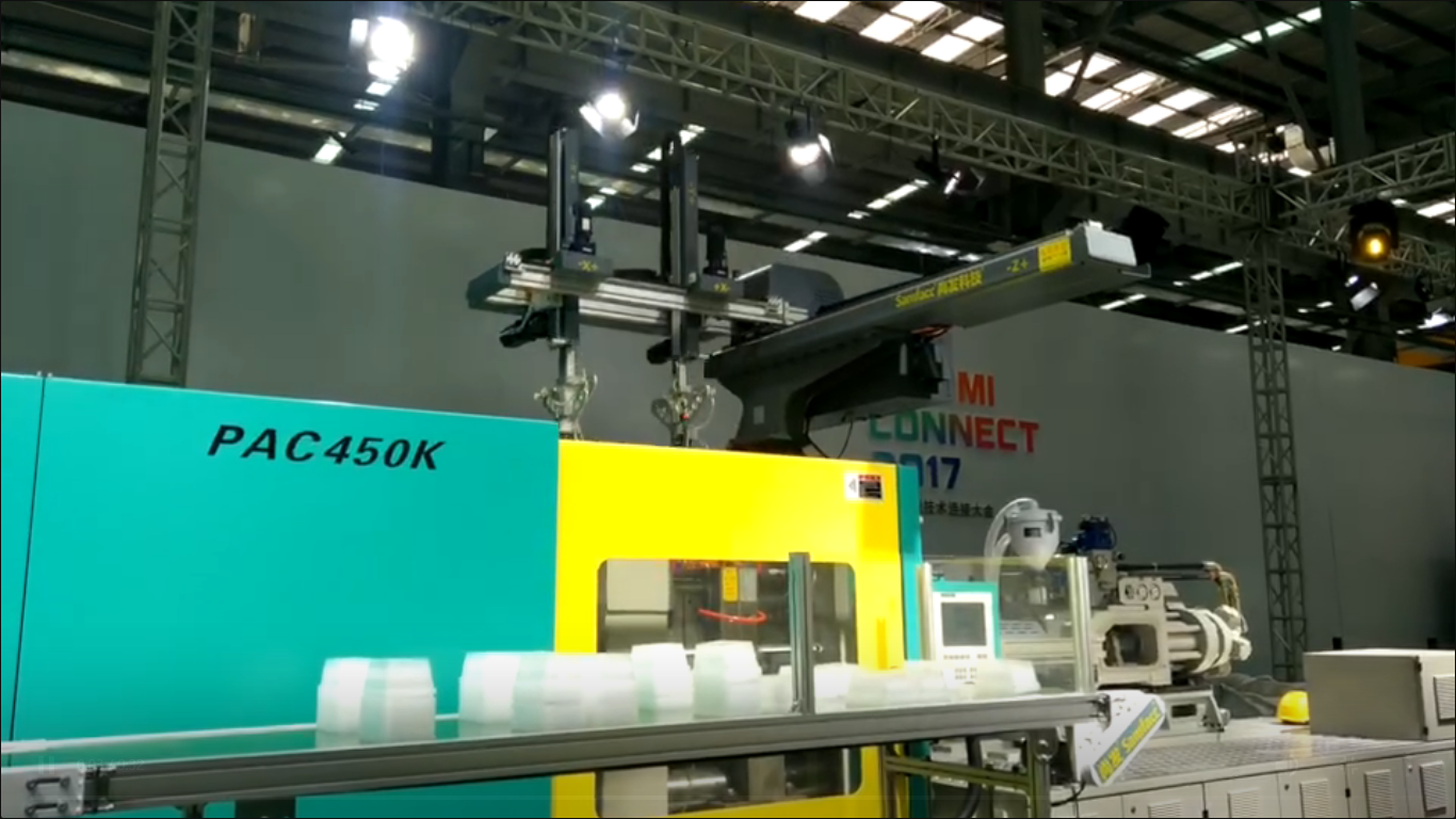
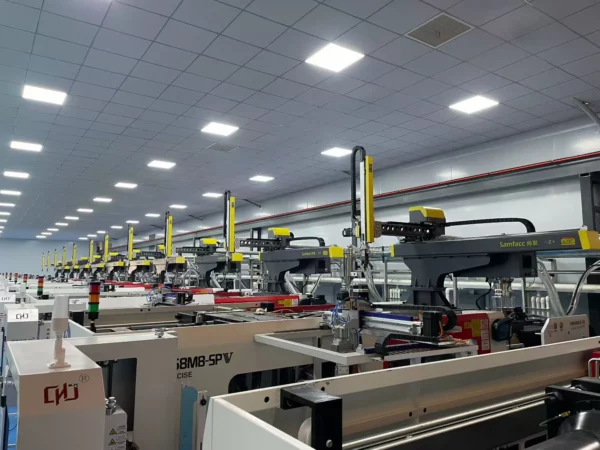
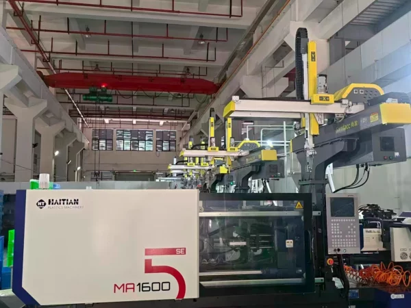
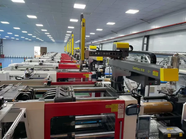
One of the best examples of the efficiency of the hardware combination in action is special-purpose robots in the automation of plastics production. For instance, the Samfacc SFN Series Standard Robot includes a highly sophisticated 3-to-5 axis robot arm control system made to work together with 120-ton to 800-ton injection molding machines (IMMs). It has a direct connection between the main controller and the controller interface of the molding machine through 18 built-in standard programs and 80 memory slots for teaching and additional storage space to keep up to 100 mold profiles.
Through the implementation of a high-speed belt drive system and coordinated AC servo control, the total cycle time of the process is reduced to 3 to 6 seconds. The servo system decreases the overhead clearance while providing high positional accuracy when taking out multi-cavity parts such as PET preforms or cosmetic pump components.
4. How to Choose the Right Robot Arm Control System?
Selecting or evaluating a Robot Arm Control System requires matching core engineering metrics against specific production demands:
| Evaluation Criteria | Key Parameters / Standards | Target Value / Selection Note |
| Axis Support & Expansion | Axis count, communication bus | Choose systems supporting 4–6 motion axes plus auxiliary external axes via EtherCAT. |
| Loop Speed & Interpolation | Motion cycle time, frequency bandwidth | Look for interpolation cycle periods ≤ 1 ms to support fast, smooth movement routines. |
| HMI & Usability | Interface simplicity, teaching box design | Touch-screen interfaces with graphical programming reduce training overhead significantly. |
| Recipe Storage Capacity | Profile storage, program memory slots | Look for memory capable of storing ≥ 50 mold routines to streamline quick line changeovers. |
| Build Integrity & Testing | Burn-in testing, safety certifications | Require ISO9001 and CE compliance alongside 24–36 hour continuous factory stress tests. |
5. Conclusion
The powerful Robot Arm Control System determines the speed, accuracy, and stability of operations performed on the automated production lines. Gaining knowledge of the communication between the controller, servomotor drives, actuators, and sensors helps engineers choose hardware, which will shorten the cycle times and ensure constant throughput for an extended period.
If you have any questions concerning the choice of a robot arm control system, the automated process of parts removal, or customized injection molding automation, do not hesitate to get in touch with Samfacc at any convenient time. We are happy to help you out!